
Aluminium Scaffold Base Jacks & Adjustable Legs: Spindle Engagement, Levelling Limits & Ground Bearing Guide (2026)
Specify aluminium scaffold base jacks and adjustable legs with verified engagement, levelling limits and ground bearing checks. Use the RFQ checklist to compare.
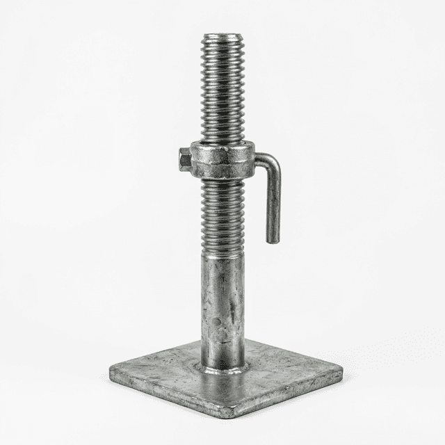
One-line buyer takeaway: Procure scaffold base jacks against the exact tower model: require approved spindle engagement, maximum working extension, retention details and ground support arrangements before comparing prices.
For fleet procurement managers, engineering specifiers and hire companies, scaffold base jacks and adjustable legs are assembly-specific parts. A replacement that slides into a frame is not necessarily a compatible or adequately rated replacement. Scaffold castor wheels and static base plates also serve different support arrangements.
Have an assembly to replace? Request a model-specific base-jack quotation with the tower model, existing part number, required adjustment and destination market.
Scope and review date — 3 November 2026: This global English-language procurement guide provides document checks and illustrative arithmetic for aluminium scaffold tower foundations. It is not a site design, product test report or approval of any pictured part. US regulatory requirements, UK guidance and European tower standards have different scopes; destination rules and the exact assembly instructions govern. For Australia/New Zealand or another market, obtain the applicable local design basis from the supplier or designer; no local clause-level compliance is asserted here.
1. Static Base Jacks vs. Rolling Castor Wheels: Operational Boundaries
Start with the approved configuration of the aluminium scaffold tower, rather than selecting a foot solely from the ground slope.
PASMA's EN 1004 revision guide distinguishes mobile towers on wheels from towers on base plates and points to BS 1139-6 for UK configurations outside EN 1004's scope. Replacing wheels with static jacks does not automatically preserve the original tower's compliance basis.
- Routine relocation: retain the approved castor assembly and its specified locking and adjustment arrangements. Static jacks do not provide rolling mobility.
- Stationary maintenance: consider a base-jack package only if the manufacturer or designer approves that tower configuration, including bracing and stabilisation.
- Sloping ground, ramps or stairs: obtain a permitted configuration and support assessment. There is no universal 1.5° castor limit or 5° base-jack allowance established by the sources cited here. Levelling travel alone does not establish slope suitability.
HSE's tower scaffold guidance calls for firm, level ground with properly supported locked castors or base plates, and warns against incompatible components. Assess erection and movement separately; a support adequate in a stationary position may not provide an adequate travel route.
2. Spindle Engagement Mechanics & Over-Extension Failure Modes
Define engagement and extension separately
Internal engagement (L1) is the supported overlap inside the receiving tube. Working extension (L2) is the exposed adjustment dimension, measured from the datum identified on the approved drawing. Thread engagement inside the adjusting nut is a separate dimension. An advertised overall spindle length cannot replace any of these checks.
The public references below do not substantiate a universal 150 mm insertion depth or 250–300 mm maximum extension for all aluminium towers. Request both limits for the exact assembly, together with the permissible leg reaction at the proposed extension. If the supplier cannot identify the datum and limit, hold the part for clarification.
Why over-extension matters
An exposed spindle carries compression and may also carry bending from eccentric loading. Increasing exposed length or reducing tube engagement can increase deformation and instability risk. The actual response depends on the thread-root section, material, fit, load eccentricity and assembly restraint. A generic stress equation cannot establish the tower's working capacity.
Look for bent spindles, flared receiving tubes, damaged threads and nuts that bind. These are reasons to quarantine a part for assessment, rather than force it into service.
Retention is not the working-limit rating
Ask how the approved design prevents unintended separation and how that feature is inspected. A pin, captive nut or other retaining arrangement is not an invitation to operate at its mechanical end stop. Use the stated working limit; do not drill a spindle or add a stop pin to create apparent compatibility.
3. Metallurgy and Thread Architecture: Solid Steel vs. Hollow Aluminium
Material choice follows the rated assembly
Solid steel may offer a robust handling arrangement but adds mass. Hollow aluminium can reduce mass, but its geometry, alloy, temper and surface condition must be specified. Neither material establishes an allowable load, fixed percentage weight saving or maintenance interval on its own.
Compare actual unit mass, material documentation and the allowable load at the required extension. Ask about corrosion protection, dissimilar-metal interfaces and replacement criteria for worn threads. Specify the finish by the approved drawing and exposure conditions; a single coating thickness is not a universal requirement for every steel component.
Thread profile, pitch and nut must match
Acme and metric trapezoidal threads are different profiles; similar appearance does not establish interchangeability. Record profile, diameter, pitch, lead and matching nut part number. Do not substitute an ordinary fastener or assume a coarse thread is self-cleaning or self-locking in every condition.
Use the manufacturer's cleaning and lubrication instructions. Do not introduce sand or mortar as an improvised receiving test, or force a nut through contaminated threads.
4. Engineering Comparison Table: Base Support Hardware
Use this matrix to compare documentation needs. It contains no generic certified loads or extension ratings: those must be supplied for the actual part and complete tower arrangement.
| Base support configuration | When to consider it | Evidence to request | Limit that controls acceptance | Procurement hold point |
|---|---|---|---|---|
| Solid steel screw base jack | Approved stationary tower package | Part drawing, material/finish record, load vs. extension data | Allowable leg reaction at installed extension | Similar thread diameter is insufficient |
| Hollow aluminium adjustable leg | Approved assembly where handling mass matters | Alloy/temper, wall section, unit mass, matching nut | Rated assembly and wear limits | Do not infer capacity from alloy designation |
| Adjustable castor wheel assembly | Approved mobile configuration | Wheel, spindle, brake and tower compatibility records | Complete castor rating and tower instructions | Check assembly rating, rather than tyre rating alone |
| Swivel or articulated base jack | A design requiring an inclined contact interface | Joint details, approved plate angle and configuration | Joint rating, sliding restraint and site support | Swivel angle is not an allowable tower-site slope |
| Fixed rigid base plate | Approved support requiring no screw adjustment | Spigot fit, plate drawing and support details | Foundation and complete assembly design | Do not level with improvised blocks |
| Telescopic leg extension unit | Purpose-designed stepped or stair access | Frame schedule, pin engagement and bracing details | Approved stepped configuration | Do not substitute for ordinary levelling travel |
| Outrigger levelling foot | Grounding the specified stabiliser assembly | Outrigger model, placement and foot instructions | Stabilisation design and ground support | Do not treat as a spare primary tower leg |
| U-head screw jack | A separately designed shoring arrangement | Shoring design and supported-member interface | That shoring system's design basis | Exclude from tower-foot orders unless expressly designed |
Comparing offers? Send the part drawings and required extension for a quotation and ask each supplier to identify missing compatibility or load evidence before an order is released.
5. Visual Engineering Diagram: Spindle Overlap & Ground Interface
This concept diagram locates the dimensions and interfaces to request. It is not to scale and sets no minimum engagement, maximum extension, plate size or sole-board thickness. Retention geometry varies by product; the approved drawing takes precedence.
6. Ground Bearing Pressure & Sole Board Sizing Protocol
OSHA 1926.451(c)(2) addresses base plates with mud sills or another adequate firm foundation. Footings must support the loaded scaffold without settlement or displacement. This is not a universal requirement to place timber under every support.
Worked example: area arithmetic, not a foundation approval
For an initial pressure screen, use q = R / A, where R is the design reaction on the most heavily loaded leg in kN, A is the effective bearing area in m², and q is pressure in kPa (1 kPa = 1 kN/m²). Do not divide total tower weight equally by four unless the design supports that assumption.
Illustrative assumptions only: R = 10 kN, a 150 × 150 mm plate, full contact across a 450 × 225 mm spreader, and a site-assessed allowable pressure of 100 kPa. These are hypothetical inputs, not typical ground values or supplied product ratings.
| Calculation step | Reproducible arithmetic | Interpretation |
|---|---|---|
| Bare plate area | 0.150 × 0.150 = 0.0225 m² | Assumed footprint only |
| Bare plate pressure | 10 / 0.0225 = 444.4 kPa | Exceeds the assumed 100 kPa criterion |
| Required effective area | 10 / 100 = 0.1000 m² | Pressure-only lower bound |
| Assumed spreader footprint | 0.450 × 0.225 = 0.10125 m² | Full contact has not been demonstrated |
| Pressure with full contact | 10 / 0.10125 = 98.8 kPa | Below the assumed pressure criterion only |
| Sensitivity: reaction rises to 12 kN | 12 / 0.10125 = 118.5 kPa | Same assumed footprint no longer satisfies it |
| Sensitivity: effective area falls to 0.080 m² | 10 / 0.080 = 125.0 kPa | Loss of contact changes the result |
The 98.8 kPa result does not approve a board or the site. A competent designer must establish board material, thickness, bending and local bearing resistance, plate position, contact, settlement, sliding and the underlying support. A compressive-strength value for concrete is not the load capacity of a suspended slab.
Ground-specific questions before approving support
| Supporting surface | Evidence needed | Reason to hold installation |
|---|---|---|
| Ground-bearing concrete | Slab condition, thickness, edge distance and supporting ground | Cracks, voids or unknown slab construction |
| Suspended concrete slab | Structural assessment of local and global reactions | Concrete strength alone offered as approval |
| Asphalt or bitumen | Temperature, duration and load-spreading assessment | Indentation or creep risk not assessed |
| Compacted granular fill | Compaction, depth, drainage and bearing assessment | Loose fill, buried services or recent excavation |
| Clay, sand or topsoil | Site-assessed bearing and settlement conditions | Unknown capacity, moisture change or soft patches |
| Raised access floor | Panel, pedestal, subfloor and spreader design | Panel rating treated as a ground pressure rating |
| Pavers on a sand bed | Paver condition and underlying bedding/support assessment | Rocking, cracking or uncertain load distribution |
7. B2B Technical RFQ Checklist: Sourcing Base Jacks & Adjustable Spindles
Use the following six-point schedule in a tender for replacement scaffold base jacks:
- 1. Assembly identity and dimensions: tower manufacturer/model, frame revision, part numbers, tube inside diameter, spindle outside diameter, insertion datum, minimum engagement and maximum working extension. Tube outside diameter alone does not establish clearance.
- 2. Retention and adjustment: drawing of the approved retaining arrangement, extension markings, separation prevention and unloaded inspection procedure.
- 3. Material and finish: specified grade/temper, applicable material certificate, finish and corrosion precautions. Ask which documents are actually available for the quoted batch.
- 4. Matched thread and nut: profile, diameter, pitch/lead, nut material, tolerances, cleaning and lubrication instructions, and wear/rejection criteria.
- 5. Rating evidence: allowable leg reaction at the required extension, load cases and configuration covered, plus the relevant report or design reference. Distinguish allowable load from proof load and ultimate failure load.
- 6. Ground interface and market: base plate drawing, load-spreader requirements, site support assumptions, destination standard/design basis, inspection records and traceable batch identification.
8. Receiving Inspection & Fleet Maintenance Acceptance Checklist
These are proposed document and visual checks, not a substitute for the manufacturer's inspection procedure or a structural load test.
- Match the paperwork: compare order, delivered part number, approved drawing revision and batch records. Hold undocumented substitutions.
- Measure the actual interface: check tube inside diameter and spindle dimensions against drawing tolerances. Confirm fit on a clean, unloaded approved assembly without forcing parts.
- Check the adjustment range: follow the manual to verify motion, markings and retention within the permitted working range. Do not deliberately wind past a working limit to test a stop.
- Inspect condition: quarantine bent spindles, damaged thread flanks, cracked plates, distorted nuts or missing retaining features. Assess finish using the agreed specification.
- Record the result: retain dimensions, photographs, drawing reference and disposition for the inspected batch; agree the sampling plan with the supplier.
- Release the complete configuration: confirm the support design and required scaffold outriggers, bracing and instructions are available before deployment. A depot fit check is not site approval.
9. Frequently Asked Questions (FAQ)
What is the minimum internal spindle engagement required inside a scaffold tube?
Use the minimum engagement and maximum extension specified for the exact tower and leg assembly. The public sources cited here do not establish a universal 150 mm minimum for every adjustable leg. Require a dimensioned drawing and assembly instructions before approving a replacement.
When should procurement teams specify static base jacks instead of castor wheels?
Specify static base jacks only where the tower manufacturer or a suitable design expressly permits that configuration. They may suit stationary work, but changing from castors changes the support arrangement and can change the applicable standard. Ground support and stability still need verification.
What is the difference between solid steel spindles and hollow aluminium adjustable legs?
Steel and aluminium assemblies differ in mass, stiffness, corrosion behaviour and wear. Compare the actual part drawings, weighed component mass, material certificates and allowable loads at the specified extension. Neither material alone establishes a safe working load or a universal weight saving.
Can scaffold base jacks be used on gradients steeper than 5 degrees?
There is no universal 5-degree permission or prohibition established by the cited sources. A jack levels the frame within its approved adjustment range; it does not by itself approve a sloping site. Obtain a permitted configuration and site support assessment for ramps, stairs or uneven levels.
What prevents a threaded spindle from unscrewing past its permitted extension limit?
Depending on the approved design, a retaining feature, stop or other arrangement may limit separation. Ask for its drawing and inspection method. A retention stop is not proof that every position up to that stop is an allowable working extension; follow the assembly limit and markings.
Are timber soleplates mandatory under scaffold base jacks?
The requirement is adequate support for the loaded scaffold. OSHA 1926.451(c)(2) addresses base plates with mud sills or another adequate firm foundation, rather than a universal timber-only rule. The site design must establish whether timber boards, engineered spreaders or direct support are appropriate.
How does spindle extension affect the permissible tower leg load?
Greater exposed length can increase bending and buckling sensitivity, but no universal percentage derating applies. Require the allowable leg reaction for the actual extension and configuration from the manufacturer or designer. A component test load or ultimate failure load is not its allowable working load.
10. Request a Complete Tower Foundation Quotation
For a single-width scaffold tower or double-width scaffold tower, send the complete configuration rather than ordering by spindle diameter alone.
Request a foundation-component quotation with:
- Tower manufacturer, model, frame revision and existing part numbers or photographs.
- Platform height and footprint, required leg adjustment and intended loading.
- Ground or floor construction, level changes and available support assessment.
- Destination market, required documentation, quantity and delivery requirements.
Request model-specific drawings, compatibility confirmation, allowable loads at the required extension, available material/test documentation and packaging details with the offer. Confirm the scope of those records before purchase; this guide and its illustrations do not certify a component or installation.
Sources & References
Public sources checked on 3 November 2026. The source roles below are limited to what each page supports; this review does not claim a full-text standards assessment or physical testing.
- OSHA — 29 CFR 1926.451, General requirements: US construction scaffold regulation. Paragraphs (c)(2)–(3) address foundations and upright support; this page does not establish a universal adjustable-leg insertion depth.
- HSE — Tower scaffolds: UK guidance on tower stability, compatible components, assembly instructions and inspection. It supports the ground/support checks, rather than the hypothetical bearing values above.
- PASMA — Your complete guide to the EN 1004 revision 2020: Historical revision guidance and a scope distinction between mobile towers and other configurations, including towers on base plates. It is not a current clause-by-clause certificate for a particular tower.