
Aluminium Scaffold Outriggers vs Stabilizers: Sizing Rules, Wind Load Limits & EN 1004 Stability Guide (2026)
Compare aluminium scaffold outriggers and stabilizers, check sizing and wind limits, and use the RFQ checklist to request a documented tower configuration.
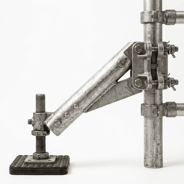
One-line buyer decision: Order scaffold outriggers or stabilizers as part of a documented tower configuration: match the support part numbers, deployed footprint, platform height, wind instructions, and replacement parts before approving the purchase order.
For buyers of an aluminium scaffold tower, the useful comparison is between complete support arrangements. An accessory called an “outrigger” is not automatically compatible with another supplier's tower, and a wider-looking base does not establish a safe working height.
Scope and review date — October 25, 2026: This English-language guide supports global procurement of conventional mobile access towers. EN 1004 is a European design-standard framework, not a single worldwide workplace law. UK and Australian guidance below is identified by jurisdiction; other markets require their own local checks. Stair, bridge, cantilever, sheeted, and other special towers need separate assessment.
Method: This is an editorial review of the three public sources listed below, translated into an RFQ decision matrix and receiving checklist. The diagram and worked example are illustrative; no physical testing or model-specific stability certification is claimed. Use the actual tower manual and competent site assessment for assembly and operation.
If you already have a project, send the platform height, available floor space, and destination market for a configuration quotation.
1. Outriggers vs. Stabilizers: Compare the Actual Assembly
Supplier terminology varies. In this guide, a footpad stabilizer means an inclined support ending in a ground pad, while a castor-equipped outrigger means a base extension with an additional wheel. Check the manufacturer's drawings rather than selecting by name alone. A support may be fixed or telescopic, with different extension positions and attachment details.
A. Footpad Stabilizers
The pad and its clamps form part of the support arrangement while the tower is stationary. Procurement checks should cover contact with the intended surface, compatible tube dimensions, clamp locations, and any telescopic locking mechanism. Repositioning must follow the manual, including how supports are raised and reset; there is no generic transit clearance specified here.
B. Castor-Equipped Outriggers
A wheeled extension can widen the support arrangement, but wheel ratings, brakes, attachment details, and moving instructions still need verification. Its presence does not authorize work while rolling. HSE's tower guidance prohibits moving a tower with people or materials aboard and calls for reducing its height to no more than 4 m before moving. Apply the manufacturer's instructions and any stricter local requirements.
Structural Comparison Matrix
| Procurement check | Footpad stabilizer | Castor-equipped outrigger | Base without added supports |
|---|---|---|---|
| Ground contact | Pad condition, articulation, and full contact | Wheel, stem, brake, and surface suitability | Main castor support and brake condition |
| Deployed footprint | Pad-to-pad envelope from the manual | Outer wheel envelope from the manual | Frame dimensions alone are insufficient |
| Compatibility | Exact clamps, tubes, and attachment positions | Approved extension and castor assembly | Confirm the manual permits this setup |
| Height selection | Support schedule for the selected platform height | Height and load limits for that configuration | No universal low-height exemption |
| Repositioning | Follow the prescribed support reset procedure | Follow the documented moving procedure | Follow moving limits and ground checks |
| Receiving inspection | Pins, clamps, pad attachment, and damage | Pins, brakes, wheels, stems, and damage | Bracing, frame, castors, and missing parts |
| Lifecycle cost | Obtain pad and clamp spare-part prices | Obtain wheel, brake, and stem spare-part prices | Compare complete compliant packages |
2. Stability Physics: Why a Ratio Alone Is Insufficient
A height-to-base ratio does not account for support contact, load position, horizontal work forces, or wind exposure. Use the model-specific component schedule rather than treating a “3:1” rule as approval to omit supports. The public sources reviewed here do not establish that EN 1004-1:2020 abolished every historical ratio rule worldwide.
For a simplified horizontal force, overturning moment is M = F × h, where F is force and h is its height above the pivot. At the same force, doubling the height doubles that contribution; it does not increase exponentially. The restoring contribution depends on weight and the horizontal distance to the relevant support edge. Actual design checks include multiple load cases, directions, support reactions, and the prescribed design factors.
Illustrative arithmetic only: A hypothetical 200 N horizontal force acting 4 m above a pivot contributes 800 Nm. At 8 m it contributes 1,600 Nm. Neither result establishes a tower rating or an allowable worker force. Do not count a worker as guaranteed stabilizing ballast or apply an assumed universal safety factor.
For a single-width scaffold tower or a double-width scaffold tower, request the actual footprint and support layout at the required platform height. Frame width alone cannot resolve the selection.
3. Visual Guide: Support Footprint and Force Direction
The schematic shows a possible overturning edge and the difference between frame width and support footprint. It is not to scale and shows only two supports in elevation; it is not a plan-view installation layout. Clamp positions, support angles, and dimensions must come from the product manual.
4. Stabilizer Sizing Matrix: Match the Site to the Manual
There is no universal SP7/SP10/SP15 sizing table across manufacturers. A model label, arm length, or platform-height band is meaningful only alongside its supplier's approved configuration. The following matrix defines what a buyer needs to obtain; it does not assign unverified “certified” dimensions.
| Site or selection case | Information to request | Purchase decision |
|---|---|---|
| Low platform, including below 2.5 m | Exact component list and support requirement at that height | Do not assume supports are optional because the platform is low |
| Single-width tower | Deployed length and width, support part numbers, and clamp positions | Confirm the whole footprint fits the site |
| Double-width tower | Its own height/load schedule and complete support layout | Do not transfer a narrow-tower schedule |
| Higher indoor work | Approved indoor platform height and exposure conditions | Check that open doors or building openings do not invalidate the intended conditions |
| Outdoor work | Permitted height, working wind limit, and storm procedure | Reject an indoor-only quotation for outdoor use |
| Against a facade | A documented wall-side arrangement and any tie requirements | Do not rotate or remove arms by improvisation |
| Narrow corridor | An approved reduced-footprint alternative or another access method | Hold the order if the normal support envelope does not fit |
| Replacement support package | Exact tower series, part revision, tube interface, and compatibility confirmation | Match the approved assembly rather than buying a similar-looking arm |
Worked procurement example — hypothetical inputs: A supplier's drawing for the requested height shows a deployed footprint of 3.0 m × 2.8 m. The measured corridor width is 2.6 m. The support width exceeds the corridor by 2.8 − 2.6 = 0.2 m, before any access clearance is considered. The RFQ outcome is “configuration unresolved”: request a documented alternative or select different access equipment. Shortening a telescopic arm until it fits is not approval.
PASMA's EN 1004 revision guide describes the standard's scope as platform heights up to 8 m outdoors and 12 m indoors, including towers below 2.5 m. These are scope boundaries, not a promise that every product reaches those heights. Adding ties does not by itself approve a taller or otherwise non-standard tower.
For a quotation comparison, ask for the support part numbers and deployed drawing alongside the tower price. This exposes an incomplete accessory allowance before the order is released.
5. Wind Limits, Restricted Footprints, and Ballast
Separate Working Limits from Other Wind Conditions
The PASMA public guide states a maximum working guidance value of 17 mph, approximately 7.6 m/s or 27 km/h, alongside its discussion of design wind loading. A design pressure is not interchangeable with a permission to keep working at a particular measured speed.
Do not treat 12.5 m/s (45 km/h, about 28 mph) as a universal working limit under EN 1004. Obtain the model's working limit, instructions for an unattended tower, and the forecast conditions requiring sheltering or dismantling. Follow the lower applicable manufacturer or site limit, allow for gusts and local exposure, and plan the response before weather deteriorates. HSE says towers must not be used in strong winds.
The site plan should identify who monitors conditions, how workers descend, and who implements the manual's securing or dismantling procedure. Do not assume a tower can safely be moved once winds are strong. Sheeting, banners, and attached equipment can change wind loading and require explicit approval.
Restricted Footprints Are a Configuration Question
A wall, corridor, or obstacle may prevent the documented support layout. Obtain the manufacturer's permitted alternative or a competent designer's applicable design. There is no general instruction here to position a tower within 150 mm of a wall, rotate supports parallel to it, or fit ties at a fixed spacing. A facade is not automatically a structural anchor or an adequate support.
If ballast is specified, obtain its type, mass, location, attachment, and retention method for the exact configuration. Do not replace specified weights with sandbags, water containers, or site materials without explicit design approval. Ballast is not a generic substitute for missing supports, and tie capacity includes the anchor and supporting structure, not just the coupling hardware.
6. Coupler Compatibility and Clamp Test Evidence
A stabilizer's load path includes its clamps, tube interface, extension lock, and ground contact. Ask the supplier to identify the relevant assembly drawing, tightening method, acceptance criteria, and test report for the quoted components.
There is no generic 20–25 Nm tightening setting or 4.0 kN slip threshold established by the public sources reviewed for this article. A test value for a different clamp, tube diameter, material, or tightening condition is not evidence for the offered assembly. Do not cite an unverified EN 1004 clause number as a purchasing requirement.
Use the manufacturer's specified tools and tightening instructions. If they are missing, hold acceptance pending clarification rather than selecting a torque from another scaffolding system. When reviewing aluminium scaffold wall thickness, include the actual tube and clamp combination in the evidence request; thickness alone does not approve the connection.
7. Procurement and Receiving QA Checklist
Use this six-point checklist with the sizing matrix. Record the document revision and the person resolving each open item before releasing the purchase order or accepting substitutions.
- 1. Configuration and compliance evidence: Match the tower series, platform height, intended exposure, component list, and applicable standard to the quotation. Verify that any certificate or test report identifies the offered configuration and issuing organization.
- 2. Clamp and interface compatibility: Record support part numbers, tube interface, attachment positions, and the manufacturer's tightening method. Obtain relevant connection test evidence and reject unsupported substitutions.
- 3. Footpads or castors: Check the delivered part against its drawing, surface suitability, attachment, condition, and any required brake or articulation function. Identify available replacement parts.
- 4. Telescopic locking: Confirm every prescribed pin, latch, or other locking device engages as the manual requires at the selected extension. Do not invent a universal pin design or accept missing locks.
- 5. Condition and traceability: Inspect for deformation, cracks, damaged welds, loose fittings, and missing identification. Refer questionable parts to the supplier's acceptance criteria; a visual check cannot establish weld penetration.
- 6. Handover package: Obtain the current user manual, deployed drawing, wind response instructions, inspection requirements, spare-part list, and any approved ballast or tie schedule. Include these deliverables in the purchase order.
8. Fleet Maintenance and Inspection Boundaries
Before use, check the assembled supports, contact points, clamps, brakes, and locks as part of the tower inspection. Quarantine parts with suspected cracks, deformation, damaged threads, missing pads, or defective locks for competent assessment. Use the manufacturer's repair and withdrawal criteria; this guide does not invent universal dent, bowing, gouge, or torque tolerances.
For UK construction work, HSE specifies inspection after assembly and every seven days where a person could fall 2 m or more. Other work and jurisdictions have their own inspection requirements. Safe Work Australia describes risk-management and inspection duties and directs users to the relevant WHS regulator. A UK inspection interval is not a worldwide rule.
Reassess the tower after relocation, alteration, damage, or weather that could affect stability, following the manual and local requirements. Keep inspection and component-replacement records with the fleet asset so the approved setup can be reconstructed.
9. Frequently Asked Questions
What is the difference between scaffold outriggers and stabilizers?
Suppliers may use these names differently. Compare the actual footpad or castor, attachment points, and approved configuration in the tower manual; the product name alone does not establish compatibility or permission to move an occupied tower.
Can a 3:1 height-to-base ratio replace the tower manual?
No. For an EN 1004 tower, use the manufacturer's component schedule and setup instructions for the exact platform height and exposure. A ratio alone does not verify stability; this guide does not claim that every jurisdiction abolished ratio rules in 2020.
What wind limit should buyers specify for outdoor towers?
Ask for separate working, unattended, and dismantling limits. PASMA's public EN 1004 guide gives a maximum working guidance value of 17 mph (about 7.6 m/s). Follow any lower manufacturer or site limit; 12.5 m/s is not a universal permission to keep working.
Does EN 1004 allow every tower to reach 8 m outdoors and 12 m indoors?
No. Those are platform-height scope limits described by PASMA, not the rating of every tower. The exact model, support layout, load, exposure, and manufacturer instructions determine the permitted height. Taller or special configurations need a separate applicable design basis.
Can ballast or wall ties replace stabilizers in a narrow corridor?
Only where the manufacturer documents that exact alternative or a competent designer provides an appropriate design. Obtain the ballast type, mass, position and retention, or tie and anchor requirements. Do not invent a wall gap, tie spacing, or ballast substitution.
What torque should be used on stabilizer clamps?
Use the value and tightening method specified for the exact clamp and tower tube. There is no generic 20–25 Nm setting or 4 kN slip rating established by this guide. Request the relevant instructions and test evidence before accepting a substitute component.
How often should scaffold stabilizers be inspected?
Check the assembled tower and its supports before use and after changes or events that could affect stability. Apply local inspection rules. HSE states a seven-day inspection interval for UK construction towers where a person could fall 2 m or more; that interval is not a global rule.
10. Request a Complete Configuration Quotation
When comparing scaffold outriggers, scaffold castor wheels, and complete tower packages, compare the delivered configuration and documentation as well as the accessory price. A missing support drawing, incompatible spare part, or unresolved footprint can prevent deployment even when the tower frames have arrived.
Contact the commercial team with the required platform height, tower width, available floor space, indoor/outdoor exposure, destination market, and quantity. Request the matching support schedule, current manual, available test evidence, and a quotation that identifies any unresolved configuration requirements. Confirm the scope of supplied evidence before approving the order.
Sources & References
Public pages reviewed on October 25, 2026. These are guidance sources, not full-text standards or certificates for a particular product.
- PASMA — Your complete guide to the EN 1004 revision 2020: standard scope, platform-height boundaries, and published working wind guidance.
- Health and Safety Executive — Tower scaffolds: UK assembly, stability, moving, and inspection guidance.
- Safe Work Australia — Scaffolds and scaffolding: Australian risk-management duties, inspection resources, and regulator context; not a model-specific sizing table.